Join Lazina on this episode of TechVentures to learn how to get started with the Foxhound Evaluation Board (FUT-NXP-SR150), an exclusive Future Electronics design featuring NXP’s SR150 Ultra-Wideband (UWB) technology for precise indoor positioning.
Whether you’re developing secure access control or industrial IoT solutions, this board simplifies development with Arduino compatibility, embedded software tools, and full compatibility with the NXP MCXN947 Freedom Board.
To learn more about this board, go to Future Electronics — Foxhound Evaluation Board
Related products:
See the video or read the full transcript below.
Toggle transcript
Hi! Welcome back to TechVentures.
My name is Lazina, and I’m a Technical Marketing Engineer at Future Electronics.
If you are interested in checking out any previous TechVentures videos, then please feel free to click here: Techventures video series
Foxhound (FUT-NXP-SR150) is an evaluation board designed by Future Electronics to showcase the NXP SR150 Ultra-Wideband (UWB) precise positioning and ranging solution optimized for IoT use cases.
At the heart of the board is Murata’s Type2BP, a compact UWB module with NXP’s SR150 chipset, clock, filters, and other components. It uses the Arduino form factor, making it compatible with many industry evaluation platforms. The board also includes NXP’s SE051W secure element, an OLED display, 8Mb flash memory, and built-in PCB antennas.
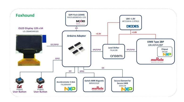
The Foxhound board has two sensors: a Murata magnetic sensor and an NXP 3-axis accelerometer. The accelerometer detects motion and helps save power by putting the UWB module into low-power mode when the board is idle and waking it up when movement is detected.
The Foxhound board includes embedded software and ready-to-use binary files, making it easy to build, load, and debug firmware, run demos, and connect to PC console software like PuTTY or Tera Term.
The evaluation platform can be used for developing industrial IoT applications like secure, hands-free physical and logical access control, indoor positioning anchors, smart home control amongst many others.

Today, I’m going to show you how to get started with the Foxhound board.
We’ll need a few things; on the hardware side we’ll need:
- 2 Foxhound shields, available exclusively through Future Electronics
- 2 of NXP’s FRDM-MCXN947 development boards, one for each Foxhound shield
- 2 USB Type-C cable
- Freedom board user guide
- jumpers
On the software side, we’ll need:
- TeraTerm
Alright, we’ve got everything we need, let’s get started!
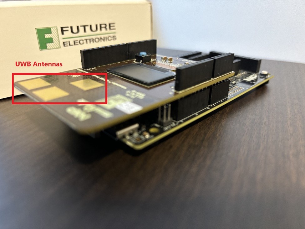
The hardware is already prepared in the box, the foxhound shield is aligned with NXP’s MCXN947 Freedom board. Just to make sure that nothing has been displaced during shipping, the UWB antennas should face the same direction as the USB-C connectors on the Freedom MCXN947 boards.
Next, power on the boards via the USB Type C connectors on the Freedom MCXN947 board using a USB Type-C cable. Plug one end of the wire to the connector, and the other to a power source.(J17 connector)
Once the boards have been powered on, the OLED display should initialize with the following startup message:
and the LED lights will flash on the Freedom boards.
Wonderful! We’ve just completed the prep work and now the fun begins, we’re ready to run our demo!
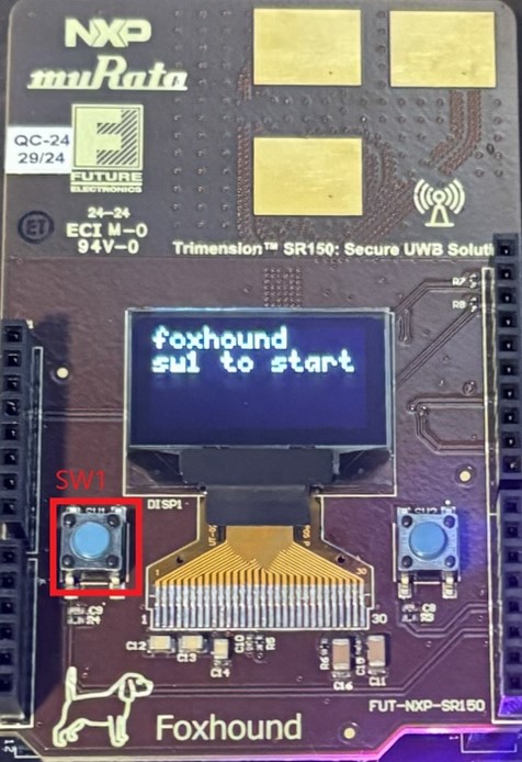
- Upon power up, you should see both displays say “foxhound sw1 to start” (Figure 3) on the OLED display. The OLED Display will indicate which board acts as a controller, and controllee.
- To Start UWB Pairing: Press Foxhound SW1 (user button 1) on both boards simultaneously to begin the pairing process.
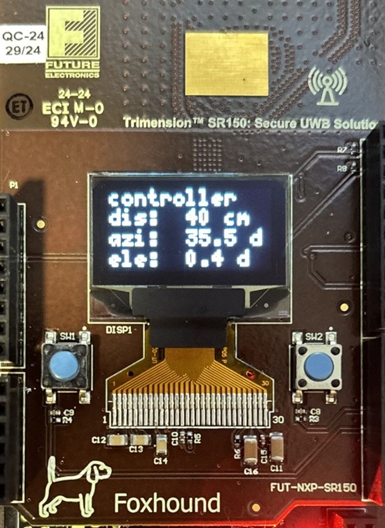
- Once paired, the modules will begin displaying data on distance, azimuth, and elevation.
- Information Displayed:
- Role: Controller/controlee
- Distance: Real-time distance between paired modules
- Azimuth: Angle of Arrival Azimuth in degrees between modules
- Elevation: Angle of Arrival Elevation in degrees between modules
- Reset Demo: Press SW1 (of FRDM-MCXN947) to restart the demo.

Please Note: The UWB demo will run for 30 minutes. After 30 minutes, a reset of both FRDM boards will be required.
The Controller, also known as the Initiator, initiates communication, while the Controlee also known as the Responder replies with the relevant data, such as two-way ranging measurements. The controller is typically stationary, acting as the anchor. This setup enables features like absolute positioning in RTLS systems with multiple Tags. For the purposes of our demo today, our ecosystem consists of only 2 boards, so it won’t really make a significant difference on which board is stationary.
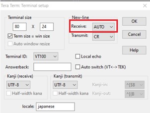
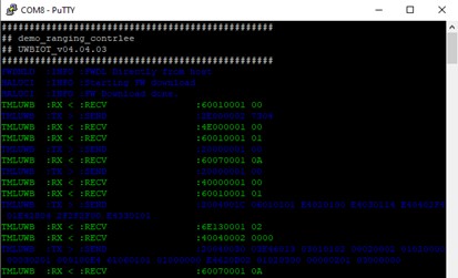
Another way to view the data between the controller and controlee is to use a terminal program of your choice to open a serial connection. I’m going to use TeraTerm. open two windows, one for each device. you could also just open one com port as both devices are broadcasting the same information. Set the baud rate to 115200, 8 data bits, no parity, 1 stop bit (8N1).
I just hit reset on the MCX boards, so that I can get a fresh start on my terminal screen. At the start of the demo, I can see the device name, firmware version, middleware version, if that kind of information is interesting to you. All the green numbers represent the payload being sent and received between the two foxhounds. if you were wondering what TMLUWB stands for, it’s for the transport mapping layer of the UWB, totally obvious right?
The measurement for distance between the two boards is also displayed, and as an added bonus, you have a historical right here, because you might not have caught it on the OLED display.
Now you know how to get started with the Foxhound board! For more information, please feel free to reach out to your local Future Electronics representative, or visit us online, at futureelectronics.com.
Thanks for watching, and I’ll catch you next time on Techventures with Lazina!