By: Jonson Chen, SZ China
Introduction
The user interface of a product is a key element that design engineers need to address to provide a compelling user experience. Touch pads, sliders and rotaries offer a more intuitive and effective way of user interaction than traditional buttons. And, designing a touch-based user interface is simplified with the NXP Touch solution. This solution includes software that is designed to work simply and seamlessly with NXP’s capacitive touch sensing hardware IP TSI that’s available on Kinetis KE15Z MCUs. Key benefits of the NXP Touch solution include:
- Robust EMC performance, noise immunity with IEC61000-4-6 standard certification with the 3V and 10V tests
- Self-cap and mutual-cap modes, supporting more than 49 touch keys.
- Liquid tolerance, effective performance even with liquid substances such as water, salt water, oil, cold steam, etc.
- High sensitivity with a sensitivity boost feature when the touch overlay on the user interface is thick (acrylic, glass)
Understanding the Hardware TSI Measurement
Touch sensing interface (TSI) provides touch sensing detection on capacitive touch sensors. The external capacitive touch sensor is typically formed on PCB and the sensor electrodes are connected to TSI input channels through the I/O pins in the device.
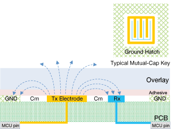
KE15Z TSI supports 2 kinds of touch sensing methods, the self-capacitive mode and the mutual-capacitive mode, as showing in the figure below.

TSI Self-Cap Mode Sensor Structure

TSI Mutual-Cap Mode Sensor Structure
Self-Capacitive Mode
The self-capacitive mode requires a single pin for each touch sensor and measures the capacitance on an electrode connected to a single TSI channel. It then converts the capacitance into a digital count by driving average current on the electrode and measuring the charge/discharge times.
The self-capacitive mode is simple, easy for touch board layout, and allows customer to design different touch pad shapes and maximize touch functionality. The typical applications of the self-capacitive mode include buttons, sliders and rotaries. Furthermore, as the self-capacitance mode tends to emit electric fields in all directions, it provides better proximity range than the mutual capacitive mode because the electric fields of the mutual mode have certain direction. KE15Z TSI self-capacitive mode offers sensitivity boost feature and supports up to 35cm proximity distance which can meet typical customer requirements in home appliance. Considering the waterproof buttons, the self-capacitive mode is preferred as it supports the shield feature which can eliminate the water impacts.
Inside the TSI IP module, the TSI scan is operated by non-overlapping clock ph1 and ph2 and a trans-conductance amplifier. There’re two phases controlled by the ph1 and ph2 respectively for the TSI scan module:
- Sample phase: The switch ph1 controls the sample phase, when ph1 turns on, the external touch electrode Cx is charged by vdd3v.
- Charge phase: The switch ph2 controls the charge phase, when ph1 turns off then ph2 turns on, the charge on the capacitor Cx flows to the internal integrated capacitor Ci, which generates the average current Icx.

TSI Self-Cap Mode Block Diagram
Mutual-Capacitive Mode
Mutual capacitive mode measures the capacitance between two electrodes connected to two TSI channels. One of the TSI channels is used as a transmit (TX) channel and the other as a receive (RX) channel.
In general, the mutual capacitive mode has lower measurement time than the self-capacitive mode. As the mutual capacitive mode detects the finger touch by the XY coordinates, it's an efficient way to implement the key matrix using less TSI channels compared to the self-capacitive mode. Furthermore, the mutual capacitive mode is preferred for the multiple buttons at one time applications.
There’re two phases controlled by the switching clock for the TSI mutual capacitive mode:
- Charge phase: The switch ph1 controls the charge phase, when ph1 turns on, the transmit channel outputs pulses which is coupled through the mutual capacitance Cm. Receiver converts the received voltage pulse (Vpre+ΔV) to the current Icharge through the resistor Rs.
- Discharge phase: The switch ph2 controls the discharge phase, when ph1 turns off then ph2 turns on, the transmit channel changes the voltage from Vdd5v to 0V. Receiver converts the received voltage change (Vpre-ΔV) to the current Idischarge through Rs.

As the integrated Ci is charged/discharged by the amplified current from receiver, the voltage Vci ramps on Ci, when the Vci becomes larger than the pre-setting Vp, the comparator will stop this TSI scan round and the digital filter will record the sample result as TSICNT.
Software Development Based on NXP Touch
NXP Touch software is designed to speed development of your touch applications and is ideal for use with KE15Z TSI IP. Available as a source code, this software features touch detection algorithms and is ideally suited for RTOS based applications. NXP Touch software employs a modular architecture with a variety of touch centric controls, modules, and electrode data objects, enabling integrated and customizable features.
NXP Touch software is based on a layered architecture with data types resembling an object-oriented approach and uses plain C language to configure electrodes, modules and controls. The library code is well suited for use in RTOSbased multi-tasking applications and in C++ object-oriented applications.
The touch sensing algorithms contained in the library use a dedicated touch sensing interface (TSI) module available on the Kinetis KE15Z MCU to detect finger touch, movement or gestures.

NXP Touch Software Block Diagram
Touch Evaluation Kit
If you’re interested in evaluating NXP touch solution for your product, you can get your touch evaluation kit: FRDM-KE15Z, FRDM-TOUCH
FRDM-KE15Z is an ultra low-cost development platform, offers two self-cap buttons on board, and compatible with Freedom touch shield FRDM-TOUCH
FRDM-TOUCH provides more touch patterns for promotion and customer evaluation, including 4 mutual cap buttons, 1 touch slide and 1 touch rotary.


