
As networks have become larger and more complex, the amount of power needed to support new Internet of Things (IoT) applications, such as connected lighting and closed-circuit security cameras, has risen above the 25W maximum supplied by the first generation of Power-over-Ethernet (PoE) standards.
To match this demand, a new universal standard for PoE, IEEE 802.3bt, was ratified in September 2018 to support power requirements up to 100W. Also referred to as ‘PoE++’, IEEE 802.3bt is backwardscompatible with the existing standards including IEEE 802.3af and 802.3at, which will remain in use by many existing PoE applications. Another benefit that the new IEEE 802.3bt standard offers is improved smart power budgeting, which enables devices to communicate their power needs.
Now ON Semiconductor has introduced new interface controllers which implement PoE++, to support the higher power demands of new IoT end-points.
The operation of a PoE power supply
PoE technology enables the transfer of power and data over Ethernet cables. The amount of power transferred is managed through the connection between the Power Sourcing Equipment (PSE) and the Powered Device (PD). The PSE can recognize the type and class of PD device, and then ensure it safely receives the appropriate amount of power.
The new IEEE 802.3bt standard adds two new types (3 and 4) and four new classes (5 to 8) of PoE devices, which increases the maximum output power the PSE can provide to 90W. Key to this increase in power is the ability to use all four paired conductors in an Ethernet cable.
With up to 90W of power available, compared to the 30W provided by the earlier IEEE 802.at standard, IEEE 802.3bt can provide both power and connectivity to new applications that would otherwise require a dedicated power source, typically the mains power grid. PoE++ will therefore simplify network topologies and provide a more robust plug-and-play user experience.
The IEEE 802.3bt standard optimizes energy management through a new Autoclass feature, which enables PDs to communicate their specific power needs to the PSE. This in turn allows each PSE to allocate the right amount of power to each PD, maximizing both the available energy and network bandwidth.
During the first class event, Autoclass automatically detects the maximum power draw from the PD and then adjusts the classification current accordingly, in a range from 40mA for Class 4 to 2.5mA for Class 0. It typically performs this classification within 81.5ms. The timing is critical, and the power detection can only be performed by an 802.3bt-qualified PSE.
After system power-up, the PD will draw the maximum power required for operation, as measured by the PSE. Using this measurement, the PSE can determine the exact power needs of the PD and adjust its output accordingly.
New controllers for PoE PD interface
To provide the high-power PoE capability specified in the IEEE 802.3bt standard, ON Semiconductor has developed a new family of compliant solutions, including the NCP1095 and NCP1096 interface controllers. These ICs incorporate all the features needed to implement a PoE interface at the PD, including detection, auto-classification and current limiting.
The NCP1095 controller operates via an external hot-swap FET, while in the case of the NCP1096 this FET is integrated into the chip, as shown in Figure 1. The integrated hot-swap FET in the NCP1096 offers lower onresistance than that of any other Type 3 or Type 4 PoE controller.
The controllers are complemented by the NCP1566 DC-DC controller, the FDMC8622 single MOSFET, and the FDMQ8203 and FDMQ8205A GreenBridge™ Quad MOSFETs, which provide a more efficient alternative to a diode bridge in PoE applications.
Together, these devices enable the designers to create highly efficient PoE interfaces with up to the standard limit of 90W of power, or up to a proprietary 100W solution if more power is needed in applications such as telecoms equipment or digital signage.

Fig. 1: Typical PoE PD circuit based on the NCP1096 PoE interface controller

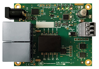
ON Semiconductors' NCP1096GEVB evaluation board


