Microchip PIC18-Q20 Microcontroller Family
Revolutionize consumer wearables with these 14/20-pin devices for sensor interfacing, real-time control and communication applications
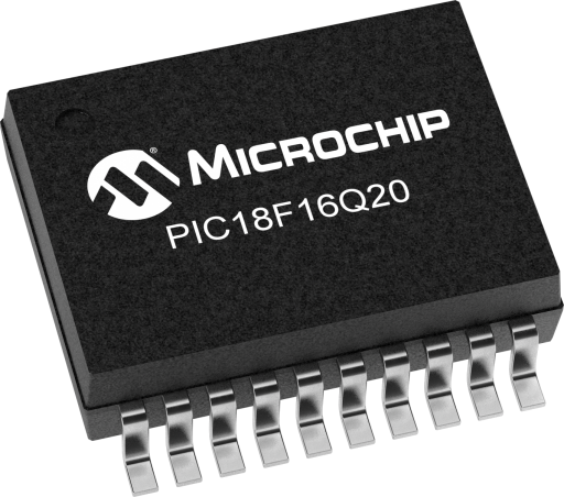
Microchip’s PIC18-Q20 microcontroller family is one of the smallest PIC18 product families available in 14/20-pin devices for sensor-interfacing, real-time control and communication applications.
This MCU family showcases the Improved Inter-Integrated Circuit® (I3C) Target module with a higher communication rate and a 10-bit 300 ksps ADC with Computation for responsive sensor designs. The microcontrollers feature a MultiVoltage I/O (MVIO) interface with multiple pins powered by VDDIO2 and VDDIO3 that allows for these pins to operate at a different voltage domain than the rest of the microcontroller.
PIC18-Q20 also feature the 8-bit Signal Routing Port module to interconnect digital peripherals without using external pins. Additional features include vectored interrupt controller with fixed latency for handling interrupts; a system bus arbiter; Direct Memory Access (DMA) capabilities; two UART with support for asynchronous modes and (for the Full-Featured UART) DMX and DALI® lighting control standards and LIN protocol; individual SPI and I2C modules; and a programmable 32-bit CRC with memory scan.
This product series also includes Memory Access Partition (MAP) featuring a user-configurable Storage Area Flash (SAF) with One-Time Programmability to support users in bootloader applications. Also included is a separate Device Information Area (DIA) to store factory calibration values, to help improve temperature sensor accuracy.
Features
- C Compiler Optimized RISC Architecture Operating Speed:
- DC – 64 MHz clock input
- 62.5 ns minimum instruction cycle
- Four Direct Memory Access (DMA) Controllers:
- Data transfers to SFR/GPR spaces from either Program Flash Memory, Data EEPROM, or SFR/GPR spaces
- User-programmable source and destination sizes
- Hardware and software-triggered data transfers
- Vectored Interrupt Capability:
- Selectable high/low priority
- Fixed interrupt latency of three instruction cycles
- Programmable vector table base address
- Backwards compatible with previous interrupt capabilities
- 128-Level Deep Hardware Stack
- Low-Current Power-on Reset (POR)
- Configurable Power-up Timer (PWRT)
- Brown-out Reset (BOR)
- Low-Power BOR (LPBOR) Option
- Windowed Watchdog Timer (WWDT):
- Watchdog Reset on too long or too short interval between watchdog clear events
- Variable prescaler selection
- Variable window size selection
Operating Characteristics - Operating Voltage Range (VDD): 1.8V to 5.5V
- Multi-Voltage I/O (MVIO) Range (VDDIO2 and VDDIO3):
- 1.62V to 5.5V (3.63V with I3C enabled)
- High-Voltage tolerant MVIO-powered pins support I3C communication down to 0.95V
- Temperature Range:
- Industrial: -40°C to 85°C
- Extended: -40°C to 125°C
Memory - Up to 64 KB of Program Flash Memory
- Up to 4 KB of Data SRAM Memory
- 256 Bytes Data EEPROM
- Memory Access Partition: The Program Flash Memory can be partitioned into:
- Application Block
- Boot Block
- Storage Area Flash (SAF) Block
- Programmable Code Protection and Write Protection
- Device Information Area (DIA) Stores:
- Temperature indicator factory calibrated data
- Fixed Voltage Reference (FVR) measurement data
- Microchip Unique Identifier
- Device Characteristics Information (DCI) Area Stores:
- Program/erase row sizes
- Pin count details
- EEPROM size
- Direct, Indirect, and Relative Addressing Modes
Power-Saving Functionality - Doze: CPU and Peripherals Running at Different Cycle Rates (CPU is typically slower)
- Idle: CPU Halted While Peripherals Operate
- Sleep: Lowest Power Consumption
- Peripheral Module Disable (PMD):
- Ability to selectively disable hardware modules to minimize active power consumption of unused peripherals
- Low-Power Mode Features:
- Sleep: < 1 µA typical @ 3V
- Operating Current:
- 48 µA @ 32 kHz, 3V, typical
Clocking Structure - High-Precision Internal Oscillator Block (HFINTOSC):
- Selectable frequencies up to 64 MHz
- ±1% at calibration
- Active Clock Tuning of HFINTOSC for better accuracy
- External High-Frequency Oscillator Block:
- Configurable HS Crystal mode up to 32 MHz
- Digital Clock Input mode
- 4x PLL with external sources
- Fail-Safe Clock Monitor: Allows for operational recovery if external clock stops
- Oscillator Start-up Timer (OST): Ensures stability of crystal oscillator sources
Programming/Debug Features - In-Circuit Serial Programming™ (ICSP™) via Two Pins
- In-Circuit Debug (ICD) with Three Breakpoints via Two Pins
- Debug Integrated On-Chip
| Digital Peripherals - Two 16-Bit Pulse-Width Modulators (PWM):
- Dual outputs for each PWM module
- Integrated 16-bit timer/counter
- Double-buffered user registers for duty cycles
- Right/Left/Center/Variable Aligned modes of operation
- Multiple clock and reset signal selections
- Timers:
- Two 16-Bit Timers (TMR0/1)
- Two 8-Bit Timers (TMR2/4) with Hardware Limit Timer (HLT)
- Two 16-Bit Universal Timers (TU16A/16B)
- Can be chained together to create a combined 32-bit timer
- Four Configurable Logic Cells (CLC): Integrated combinational and sequential logic
- One Complementary Waveform Generator (CWG):
- Rising and falling edge dead-band control
- Full-bridge, half-bridge, one-channel drive
- Multiple signal sources
- Programmable dead band
- Fault-shutdown input
- Two Capture/Compare/PWM (CCP) Modules:
- 16-bit resolution for Capture/Compare modes
- 10-bit resolution for PWM mode
- Programmable CRC with Memory Scan:
- Reliable data/program memory monitoring for Fail-Safe operation (e.g., Class B)
- Calculate 32-bit CRC over any portion of Program Flash Memory
- Communication Modules:
- Two UART Modules:
- UART1 supports LIN host and client, DMX mode, DALI gear and device protocols
- Asynchronous UART, RS-232, RS-485 compatible
- Automatic and user timed BREAK period generation
- Automatic checksums
- Programmable Stop bits (1, 1.5, and 2 Stop bits)
- Wake-up on BREAK reception
- DMA compatible
- One SPI Module:
- Configurable length bytes
- Arbitrary length data packets
- Transmit-without-receive and receive-without-transmit options
- Separate transmit and receive buffers with 2-byte FIFO and DMA capabilities
- One I2C Module, SMBus, PMBus™ Compatible:
- Supports Standard mode (100 kHz), Fast mode (400 kHz), and Fast mode Plus (1 MHz)
- 7-bit and 10-bit Addressing modes with Address Masking
- Multi-Host mode, including self-addressing
- Up to Two I3C Modules:
- Supports I3C target device mode only
- Can be used as an I2C Client module
- Adheres to MIPI I3C Basic Specification 1.0
- Transfer speeds up to 12.5 Mbps in SDR mode
Analog Peripherals - 10-Bit Analog-to-Digital Converter with Computation (ADCC):
- Up to 11 external channels and five internal channels
- Supports grouping of external channels
- Up to 300 ksps
- Automated math functions on input signals (averaging, filtering, oversampling, threshold comparison)
- Operates in Sleep
- Five internal analog channels
- Hardware Capacitive Voltage Divider (CVD) Support:
- Adjustable Sample-and-Hold capacitor array
- Guard ring digital output drive
- Automates touch sampling and reduces software size and CPU usage when touch or proximity sensing is required
- Voltage Reference:
- Fixed Voltage Reference with 1.024V, 2.048V, and 4.096V output levels
- Internal connections to ADC
|
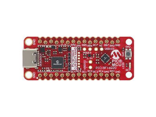
PIC18F16Q20 Curiosity Nano Evaluation Kit
EV73T25A
 | Take your next idea to market with a development board that you can keep in your pocket. With full programming and debugging capabilities, the PIC18F16Q20 Curiosity Nano Evaluation Kit offers complete support for your next design. User Guide |


